OUR MAKER GROUP
© Our Maker Group 2020
Stylus Balance
The problem
I have been using a Technics SL-
But the time has come for an upgrade, and the turntables I am looking at need very careful manual adjustment of the stylus pressure and I need something to do it with.
There are a number of cheap electronic devices on the market (all under different brands, but obviously coming from the same Chinese factory) claiming to measure to 0.05g but they are suspected of being of variable quality, reliability and accuracy.
It is not uncommon in Chinese factories to have several production “lines” making the same-
There are good quality items available but they are seriously expensive. So I thought I would make my own. Couldn’t be very difficult, could it?
The specification
I wanted a device that could measure to an accuracy of 0.05g over a range of 0.7g to at least 1.5g, with an option to extend the range if required, perhaps for other purposes.
- It must be entirely mechanical, i.e. it must not require batteries.
- It would have to be easy to calibrate and verify calibration each time before use.
- It would have to be compact and robust but, as it won’t be used very often, it can be a bit fiddly to use.
- It must be easy to build using simple workshop equipment, and a 3-
D printer for body parts. - The materials need to be found around the house or garage without spending any money.
The design
I considered a number of options and decided on a balanced beam not unlike the simple see-
I therefore decided to use the same principle as hospitals used to use to measure the standing weight of patients, but perhaps a bit smaller! The idea is to have some sort of balanced beam with a sliding balance weight that is moved along a calibrated scale, preferably notched to ease registration with the calibrated values. Obviously, both the scale and the balance weight need to be accurately calibrated, and the scale needs to be easily read to the required precision.
I wanted the most likely range of values to be within the scope of a single balance weight along a shortish beam, but with the option of using a different balance weight to extend the range if necessary.
The materials
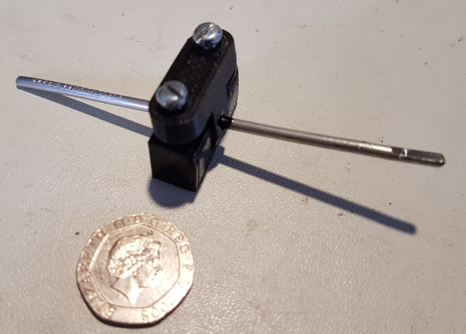
The beam itself is simply a gash length of 3mm stainless steel wire cut from a builders’ wall tie. It could have been any steel wire salvaged from some defunct bit of kit, but preferably not much thinner.
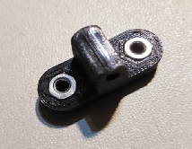
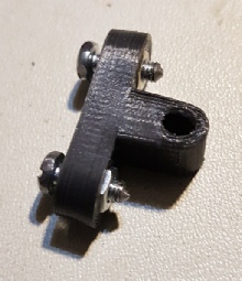
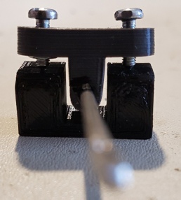
The beam head is a T-
The pivots themselves are 3mm screws or bolts bevelled to a point, and long enough to project at least 2mm through the T-
The pivot screws are held in place with hex nuts recessed into the beam head.
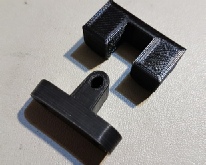
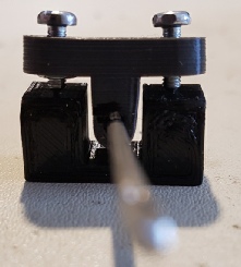
The pivots rest on a U-
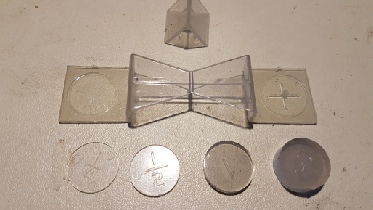
The balance weight is a piece of copper wire salvaged from some 40A mains cable. Other wire could be used, but the reason for using electrical wire is that the specification can be looked up to find the weight per metre, so a calibrated weight can be made simply by accurately measuring the length.
The test weight is similarly cut at a different length.
The tooling
A vernier gauge was used to measure the length of the beam (90mm) and to find the exact centre datum.
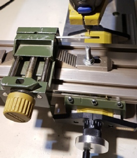
To cut the stylus pit, and mark the calibrated balance beam notches a hobby drill with a drill stand and milling bed was used. This was convenient and accurate, but I expect there are many other ways of achieving the same thing.
The T-
The calculations
The first thing was to find out how a simple wire beam could accurately register the point of a stylus at one end, and carry calibrated notches for a balance weight at the other.
The first is easy, as it comprised simply of filing a flat and drilling a pit at an exact distance (40mm) from the centre mark. To keep the beam symmetrical a corresponding flat was filed at the other end of the beam, but underneath so it didn’t get in the way of the calibrated notches.
The second is more involved as it means calculating the positions of the notches so that the steps correspond with simple values in stylus weight, e.g. 0.05g.
In basic terms we are looking for equal torque pulling downwards on both sides of the balance. This is made easier if the beam itself is balanced about it’s exact centre, which is why the two ends have exactly the same exposed length. The beam itself can then be disregarded for the remaining calculations.
The downward torque from either the stylus or the balance weight is simply the product of weight and distance from the pivot (beam centre). So if the stylus is close to one end of the beam, and the balance weight is equal to the maximum measurable weight (1.5g in this case), the notch required to achieve balance at maximum stylus weight is simply the symmetrical position at the opposite end of the beam.
By moving the weight nearer to the centre, the torque correspondingly reduces and affords a balance with lower stylus pressure without needing a different balance weight or having to place the stylus anywhere different.
It was decided that 90mm beam length was a convenient size to place on a turntable deck. This allowed the stylus and final notch to be placed 40mm each end from the pivot, leaving 5mm at each end.
Having set the limiting notch, the distance between notches can simply be calculated from the balance weight (1.5g) and the required step in weight (0.05g).
Each measured step (0.05g) is 1/30 of the maximum measured weight, so the distance of each step is 1/30th of the distance to the maximum weight distance (40mm). This gives a figure of 40/30mm, which is 1.33mm. So the remaining notches are cut at intervals of 1.33mm.
Measuring to 1/100th of a millimetre is neither easy or necessary. The important thing is to ensure every third notch is at 2mm intervals, and the intermediate ones are spaced as nearly as possible in thirds. An error even as big as 0.25mm corresponds to a weight measurement of only about 0.01g, which is too small to worry about for the present purposes. However, all measurements should be taken from the end notch as datum so there are no cumulative errors, which could otherwise become significant.
To measure the required range of 1.5g down to 0.7g, a total of 16 steps of 0.05g are needed, requiring a total of 17 notches. As can be seen from the pictures, the design happily allows for a few further notches to be used, allowing for correspondingly lighter weights.
If heavier weights are to be measured, a heavier balance weight can be used. For example a balance weight of 3g can be used to measure 1.4g to 3g in 0.1g steps. This gives an overlap with the 1.5g weight.
Contributed by:
Peter Grossi
Construction
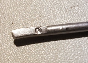
The beam is prepared by cutting to length and filing a flat for the stylus. This represents the top of the beam. A corresponding flat is filed underneath the opposite end to balance it out.
The stylus flat I marked with a drill to register the stylus accurately when used.
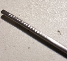
The calibration notches are cut into the top of the beam at the other end.
The T-
The screws used as pivots need to be filed to points as centrally as possible. Fitting them into the chuck of a drill and grinding them on a fairly fine file should be a good substitute for a lathe. The finer the point the better. The screws need to be long enough to project at least 2mm through the T-
Calibration
The beam is centred in the T-
With the screws in place and showing about 1mm of the points the beam assembly is placed on the U-
If the beam will not stay horizontal it may need balancing by carefully slipping it through he T-
If the beam falls either way but won’t stay in the middle the sensitivity needs adjusting by retracting the two screws by the same amount.
When finished the beam should happily stay horizontal, and will oscillate slowly about the horizontal if provoked.
Ensure the stylus notch is facing upwards.
The beam needs to be sealed in place when calibrated. I used a drip of Humbrol enamel each side rather than superglue. Sealing is important to ensure it doesn’t move off centre when handled (or dropped!).
The balance weight
Clearly the accuracy of the balance weight is reflected directly in the measurements, so it needs to be as accurate as possible. Kitchen scales and postal scales are not nearly accurate enough, but there is an easy way.
Electrical wire (solid core) is specified by size and weight, which can be looked up. For example, the wire I used is taken from 40A house mains wiring and weighs 20g per metre. So for a 1.5g weight I needed 75mm. This can be measured with an ordinary ruler, as an error up to 1mm is well within the required tolerance, although you might prefer to use a vernier.
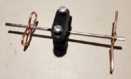
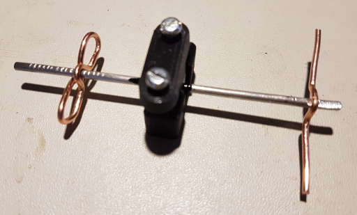
By folding the wire into a sort of pretzel it becomes easier to manage without dangling below the beam and grounding.
I cut a second weight using 50mm of wire to make 1.0g, and used this as a test “stylus” to check the beam calibration. It should be balanced by the balance weight at the 7th notch from the inside. Calculation: 1.0g – 0.7g = 0.3g; with 0.05g steps, this is 6 steps, which puts it on the 7th notch.
The picture below shows the whole assembly in balance, with the pretzel-
Usage and care
Before using the balance ensure the T-
Check the beam balances on it’s own without weights in case it has been damaged since last used, and that it oscillates freely when provoked. Then use the test weight if you want to be really sure.
When setting a stylus weight by this method it is usual to set the balance to the required weight, place the stylus on the balance , and then adjust the tonearm balance weight to achieve a level balance beam.
To measure the actual pressure of a stylus, place the balance weight to match the best guess of the expected weight, place the stylus and carefully slide the weight up and down to achieve a balance. Read the weight by counting notches (0.05g per notch, working down from 1.5g at the outer notch, or up from 0.7g at the inner notch)
Keep the balance beam, the U-
Prior to the Technics I had an AR turntable, which required manual setting of the stylus pressure, and it came with a rather natty little plastic see-